
Low-Resistance Conductive Cloth Tape for Compact EMI Grounding Paths
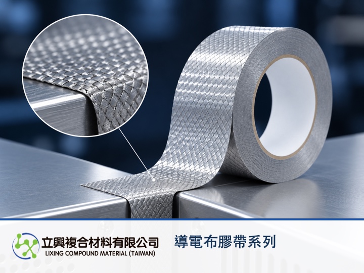
Across enclosure seams, cable turns and PCB grounding points, engineers need more than a conductive patch: they need a path that follows compact geometry while maintaining electrical continuity. The official LX-DDB conductive cloth tape specifications and applications describe a 260T plain-weave conductive fabric with conductive acrylic adhesive and a specified surface resistance of ≤ 100 mΩ. This combination gives precision electronic assemblies a flexible format for planning compact EMI grounding paths.
Low surface resistance removes a bottleneck from the grounding path
When tape bridges a metal component, cable assembly or PCB ground area, low surface resistance can support charge conduction along the intended route. The official product page specifies ≤ 100 mΩ. That number is a product specification, while the finished assembly still requires verification with its contact surfaces, overlap geometry and defined measurement conditions.
A flexible fabric carrier follows turns that rigid conductors cannot
The 260T plain-weave conductive fabric has a flexible wrapping form, and the official page identifies cable wrapping and custom die-cut shapes among its uses. In compact civilian electronics, this format can help the shielding and grounding path follow structural bends without occupying the volume of a bulky conductor.
Conductive adhesive combines positioning with electrical contact
Conductive acrylic adhesive allows the material to attach directly to a confirmed grounding surface. The product page lists surface adhesion of ≥ 1.0 kg/in under PSTC-101 and 180-degree peel strength of ≥ 1.3 kgf/in. These values support the attachment claim, but they do not replace sample testing on the intended substrate, surface preparation and ageing condition.
Custom thickness aligns die cutting with available assembly space
The official page identifies total thickness as customizable, making the series suitable where an opening, overlap width or die-cut outline must be coordinated with the assembly. When reviewing the LX-DDB conductive cloth tape product page, prepare the required thickness, width, substrate and working temperature so the sample conditions can be discussed together.
Why low surface resistance still needs a defined measurement
For a uniform, laterally large thin conducting sheet with negligible edge effects, the equal-spacing four-point-probe approximation is Rs = (π/ln 2) × (V/I). Rs is sheet resistance in Ω/□, V is the voltage measured by the inner probes in volts, and I is the current driven through the outer probes in amperes. The model explains how measured voltage and current relate to sheet resistance; its theoretical source is Smits, Measurement of Sheet Resistivities with the Four-Point Probe. Woven fabric may be anisotropic, while specimen size, probe spacing and edge proximity can change the result, so the equation cannot be used to infer a guaranteed LX-DDB value.
Turn the resistance specification into a verifiable assembly
For selection, provide the planned overlap surfaces, path direction, thickness, width, substrate, lamination method and environmental temperature. Then verify continuity before and after attachment with a documented method. For die-cutting or custom-thickness questions, use the product page to request a sample or specification consultation from Lixing.
#ConductiveClothTape #EMIShielding #Grounding #SurfaceResistance #ElectronicMaterials