
PTFE Film Tape for Bonding and Static Control: Check 10^6 Ohms, Substrate, and Ground Path
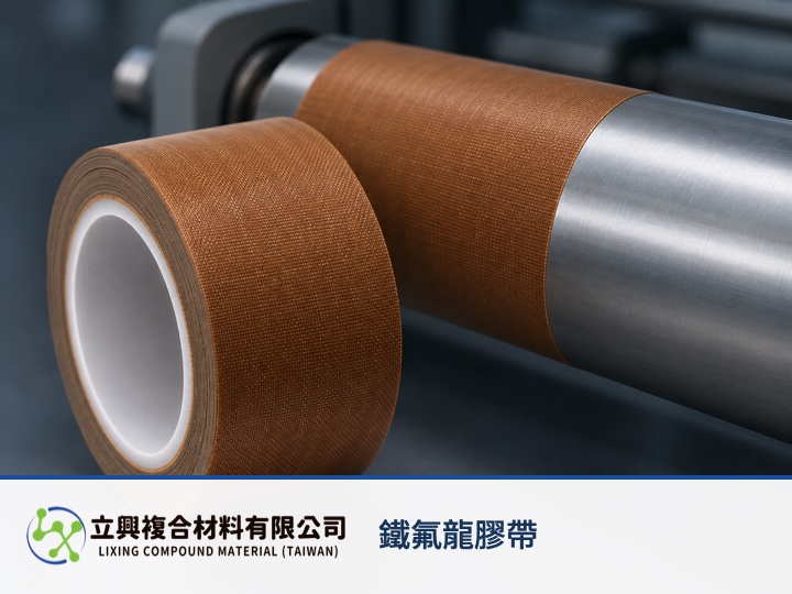
PTFE film tape can place non-stick performance, heat-resistant wrapping, adhesive fixation, and static management at one process interface. Before requesting a sample, check the substrate, service temperature, and catalog peel strength, then evaluate the 10^6-ohm value together with the real ground path and object capacitance. Those inputs explain what the tape can do, how it bonds, and whether the installed system can support a static-control plan.
A non-stick surface keeps sealing and roller zones easier to service
PTFE film tape is listed for heat sealing, roller wrapping, thermoplastic release, and electronic insulation. It places the molten-material contact zone on a replaceable film surface, concentrating cleaning and replacement at the tape interface. See the PTFE tape release mechanism for lamination for the non-stick process angle.
The 10^6-ohm value is a starting point for static-control selection
The official product page lists an anti-static value of 10^6 ohms. It supports material comparison under the catalog condition, but it is not the decay time, resistance to ground, or ESD compliance of a finished machine. The installed interface, ground point, humidity, object capacitance, and full discharge path must be evaluated together.
The adhesive holds the functional surface at the intended location
The catalog lists 0.15 mm total thickness, including 0.08 mm PTFE film and 0.07 mm adhesive, plus 850 g/25 mm peel strength. These values help compare tape form and bonding conditions. Surface energy, cleanliness, curvature, and thermal cycling can change fixation, so sampling should use the actual component and surface preparation.
Use the RC voltage-decay model to define system conditions
RC discharge can be written as V(t) = V0 × exp(-t / (R × C)). V(t) is voltage at time t in V, V0 is initial voltage in V, t is time in s, R is total effective discharge-path resistance in ohms, and C is effective object-and-system capacitance in F. The EOS/ESD Association uses an RC step response to explain how resistance and capacitance affect static decay. This lumped model does not permit the catalog's 10^6-ohm value alone to establish ESD compliance.
Validate heat, chemicals, and static behavior as separate conditions
The product page lists a maximum temperature of 260°C and describes chemical resistance and electronic insulation uses. Engineering review should separate continuous and intermittent temperature, exposed edges, and the resistance path after installation. The high-temperature PTFE tape article covers heat conditions, while chemical resistance and edge exposure covers chemical contact boundaries.
Bring the substrate, temperature, and static path to sampling
Provide the substrate, continuous and peak temperature, tape width, tension, grounding method, and target static acceptance method. Lixing Compound Material Co., Ltd. can use the formal catalog to help confirm the PTFE film tape specification and sample direction. Final acceptance remains tied to the actual process and assembly validation.
#PTFEFilmTape #AntiStatic #IndustrialTape #HeatSealing #ProcessEngineering