
How to Match a TO-220 Heat Conductive Silicone Cap by Clearance
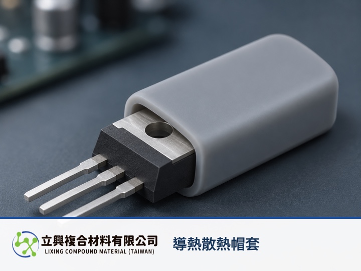
A heat conductive silicone cap fits a TO-220-class power component reliably only when the package code, body envelope and cap acceptance dimensions are compared on the same drawing basis. Lixing lists TO-220A, TO-220B, TO-220C, TP-3PA and TP-3PB options. Matching the standard package first can shorten sampling discussions while retaining thermal transfer, insulation and physical coverage.
Match length, width, height and wall thickness
The Heat Conductive Silicone Cap product page lists TO220A at 12.5 × 11.5 × 5.9 mm, TO220B at 16 × 11.5 × 5.9 mm and TO220C at 21.8 × 12.1 × 5.9 mm, each with a catalog thickness of 0.5T mm. TP-3PA is 28.5 × 17.5 × 5.9 mm at 0.5T mm, while TP-3PB is 28.8 × 18.2 × 6.6 mm at 0.8T mm. These are cap catalog dimensions, not universal limits for every component supplier.
Compare the maximum component body length, width and thickness with the minimum accepted internal cap dimensions in the same directions. Corner radii, lead shoulders and molding flash can also affect the insertion path, so the nominal TO-220 label is insufficient by itself.
Use minimum clearance to screen obvious interference
A first worst-case check is C_min = D_cap,min - D_pkg,max. C_min is minimum fit clearance, D_cap,min is the minimum accepted internal cap dimension, and D_pkg,max is the maximum accepted package dimension; all use millimetres. A zero or negative result flags possible interference. A positive result only shows that geometric clearance remains.
ASME Y14.5 supplies a common language for dimensions and tolerances so form, fit, function and interchangeability can be interpreted consistently. The equation applies when directions share a datum basis, units match and tolerances are known. It does not predict insertion force and omits silicone deformation, corner radii, roughness, thermal expansion and tolerance correlation.
The grey silicone cap serves three related needs
Physical coverage: The one-side opening and rounded rectangular outline follow the power-device body. Confirm opening direction and coverage depth against the actual component.
Thermal path: The product page lists 0.8 to 1.0 W/m·K thermal conductivity. The cap still needs reasonable contact with the component and heat-dissipation surface, and the value should not be compared without test conditions.
Electrical separation: The product page lists withstand voltage above 4 kV. A finished design must also address wall thickness, edge coverage, creepage distance, working voltage and equipment-level safety requirements.
Temperature conditions: The listed operating range is -40 to +180°C. Expansion differences among the component, cap and heat sink can change fit and contact, so validate the assembly through its intended temperature cycle.
Better sampling inputs shorten selection
For a sample request, provide the full component part number, package drawing, body tolerances, corner radii, lead-shoulder location, operating temperature, working voltage, heat-sink arrangement and assembly method. Different suppliers can use different body limits even when they all call the package TO-220.
Catalog sizes narrow the options; the actual component should still be used to check insertion, coverage and appearance after temperature cycling. For related test interpretation, see comparing UL 94 and D5470 for a TO-220 cap. For heat-flow reasoning, read Fourier-law guidance for the thermal path. Use the official product page for current specifications and sample enquiries.
Conclusion
A standard package name is the starting point. Compare the cap's minimum internal dimension with the component's maximum body dimension on a common basis, then use samples to confirm insertion force, corner contact and fit across temperature. Send the drawing and operating conditions through the product page to discuss a suitable size.