
Conductive Fabric Foam Maintains Shielding Contact Around Chassis I/O Modules
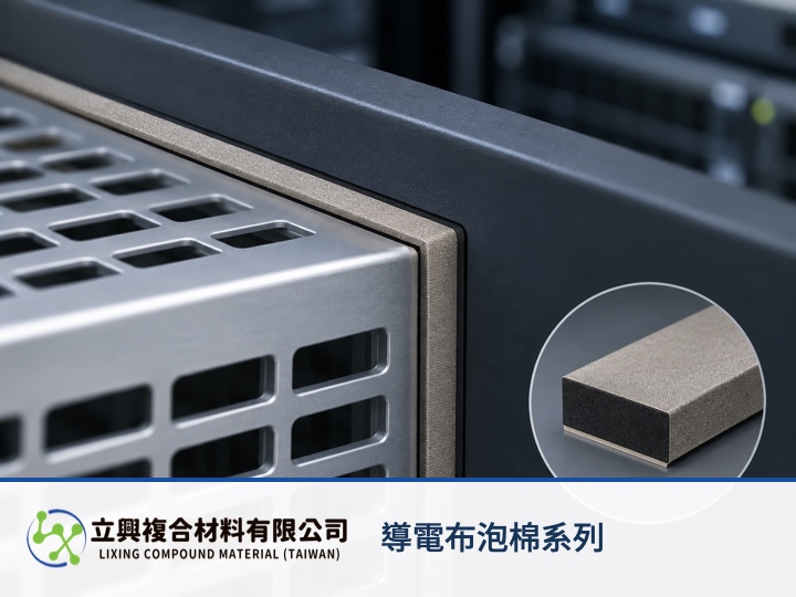
AI accelerator modules and server chassis need continuous contact around I/O openings. This LXD conductive foam uses a conductive-fabric outer surface and a compressible profile to accommodate assembly tolerance between a module cage and front panel, so shielding and grounding do not depend on rigid parts meeting perfectly. Its verified high-resilience foam core helps maintain contact pressure, giving chassis and EMC engineers a practical feature to validate during I/O seam sampling.
A compressible edge accommodates I/O opening tolerance
Variation in the chassis cutout, module frame, and panel creates an uneven perimeter gap. LXD conductive fabric foam combines a resilient foam core with conductive fabric, and its total thickness can be customized to the measured gap distribution. This format is relevant to optical transceiver cages, communications-equipment panels, and removable I/O module edges.
Low surface resistance supports a conductive contact path
The official product page lists horizontal surface resistance of ≤0.1 Ω and vertical surface resistance of ≤0.2 Ω. Conductive fabric wraps the foam and a conductive pressure-sensitive adhesive fixes the part in place, creating a planned contact path between the module frame and chassis panel. Surface resistance is a material parameter; the installed grounding result still depends on oxidation, coatings, compression, and fastening.
Verified shielding data covers 10 MHz to 1000 MHz
The registered shielding effectiveness is ≥30 dB from 10 MHz to 1000 MHz. That value provides a starting point for material sampling, while connector apertures, seam length, and enclosure grounding can change the installed result. Enclosure-level EMC acceptance should therefore use the actual module, cable, and panel configuration.
Engineering basis: the electric-field shielding ratio
NIST research on shielding gaskets expresses electric-field shielding effectiveness as SE(dB) = 20 log10(E1/E2). SE is shielding effectiveness, E1 is electric-field strength without the shield, and E2 is electric-field strength at the same point with the shield, with field strength measured in V/m. This engineering model applies only when frequency, geometry, polarization, and measurement configuration are held constant. A material-sample value cannot be treated as an enclosure guarantee.
Sampling must align the gap, surface, and frequency band
Provide the minimum and maximum I/O perimeter gap, contact-surface material and finish, target frequency band, available width, and assembly method. These inputs turn customizable thickness into a testable sample. The product page also lists tensile strength of ≥1.5 N/20mm and holding power of ≥1440 minutes under SUS304 1 kg/inch conditions, so the original test conditions must stay attached to those values.
Make the I/O seam a testable contact boundary
Procurement and engineering teams working on AI servers, optical modules, and communications chassis can begin with the foam's resilient gap-filling feature, then place resistance, target frequency, and installed EMC testing in the same sampling brief. For customized thickness and die-cut geometry, use the conductive fabric foam product page to submit drawings and gap conditions.